Vintage Speaker Maintenance - QLS-1 Woofer Recap and Base Repair
Capacitors are like small batteries, they hold an amount of charge in the dielectric material they are made of. Much like a battery, they are not forever and electrolytic capacitors in particular dry up over time requiring replacement. There are a plethora of other types of capacitors, such as film that don’t need replacing unless they test poorly. The QLS has both types in its crossover, film caps separating the upper frequency and the large “can” electrolytic capacitors make up the circuit for the woofer. The film capacitors still test fine so I chose to leave them alone for now, as I had enough to work on.

The crossovers in the QLS are located in the lowermost cavity of the speaker, in the bases. Taking the woofers out will expose the bolts holding the two parts of the tower together. I unhooked and marked all of the leads going from the circuit up to the drivers and proceeded to separate the cabinet. After removing the bolts and laying the speaker on its side, a quick knock with a dead blow dropped the bases off with a satisfying thud.

One speaker was fairly original and decent condition, the other had extensive water damage as well as some repairs from a previous owner. It was time to fix both.

This was a resistor repair done on the midbass coupler of the left speaker, while correct value on paper these did not match the other side and were hanging haphazardly in the cabinet. You don’t throw a piece of duct tape on scientific equipment and expect perfect results, so this got replaced with new quality resistors on both circuits.


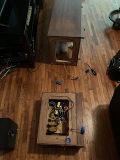
Pictured here is the crossover from the right speaker, in and out of the cabinet. Luckily I had this as a visual of the original layout and assembly from the factory to compare to as I repaired and rebuilt the other side.


Unfortunately due to product shortages I was unable to obtain the proper value capacitors for the job, so I ended up creating the values by wiring smaller capacitors in parallel. The result of using 10 10uf capacitors to substitute for the lack of a single 100uf capacitor isn’t exactly eye candy but it did the trick. The midbass couplers did not having matching capacitors, and the drivers were replaced so I updated the capacitors to Dayton Audio film.


Here is the left crossover rebuilt. The inductors were moved to reduce interference with each other, and the rusted adjustment attenuators were all replaced with new. I had to drill the back plate to make them fit, but I plan to come back later to build new plates for them when I replace the inductors and rewire the cabinets.

Same crossover now mounted to repaired base.

Both rebuilt and repaired ready for assembly.

The bases go on in the reverse as they came off. It’s easiest to do this with the towers laying on the floor so you can line up the bolt holes.

Reattaching the wires to the drivers was made easy with my labeling from earlier.


Wow! What a great write-up! Very detailed. Thanks for sharing,
ReplyDeleteI bet these beauties sound amazing now!